
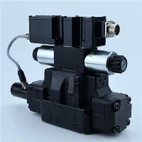
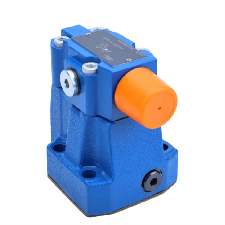
| DR Series Hydraulic High Pressure Relief Valve |
|
| Pilot operated pressure reducing structure for steady outlet pressure | |
| Max setting pressure 315 bar for heavy-duty hydraulic systems | |
| Normally open design with external pilot drain | |
| Standard ISO subplate mounting, easy installation | |
| Multiple adjustment types and pressure gauge port |
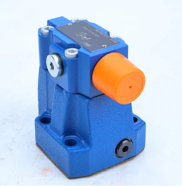
DR Series Hydraulic High Pressure Relief Valve Data sheet
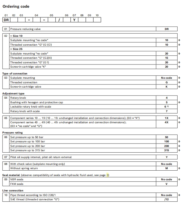
Maintenance Instructions for DR10-5-4X-315Y
Keep the hydraulic oil clean. Maintain the oil cleanliness level as required; replace the filter element and hydraulic oil regularly according to the system operating hours. Contaminated oil will cause spool sticking and pressure control failure.
Conduct regular visual inspection. Check all sealing positions, pipe joints and mounting surface for oil leakage. Replace aging or damaged seals promptly once leakage occurs.
Avoid frequent repeated adjustment of the pressure setting. If pressure deviation appears, calibrate the pressure slowly and lock the adjustment cap after setting.
If disassembly is needed, clean all components with clean hydraulic oil. Inspect the main spool, pilot poppet and spring for wear, burrs or deformation. Replace worn parts.
Do not use sharp tools to scratch the mating surfaces of the spool and sleeve. Any scratch will lead to internal leakage and unstable pressure.
Check the external Y drain line regularly. Ensure the drain line is unobstructed and free of backpressure, blockage or oil accumulation.
After maintenance, bleed air from the valve and hydraulic circuit before formal operation, then test the pressure stability and sealing condition under no-load and load status.
.
DR Series Hydraulic High Pressure Relief Valve Application Scenarios
Machine Tool Hydraulics: Provide stable low pressure supply for clamping cylinders, tool holder locking, lubrication circuits and auxiliary control loops, isolate the high-pressure main pump circuit to avoid pressure fluctuation impact on precision clamping.
Plastic Injection Molding Machines: Regulate constant pressure for mold clamping auxiliary, core pulling and ejector sub-circuits; keep secondary pressure steady during rapid injection and pressure holding stages.
Metallurgical & Steel Equipment: Control hydraulic pressure for roller gap adjustment, billet clamping and auxiliary actuator circuits under heavy-duty continuous working conditions.
Material Handling & Forklift Hydraulic Systems: Supply stable control pressure for steering, auxiliary locking and load holding circuits on heavy handling equipment.
Construction Machinery: Used in excavator, crane and road roller auxiliary hydraulic loops for pilot control, outrigger locking and accessory pressure regulation.
Hydraulic Press & Test Benches: Build independent constant-pressure secondary circuits for pressure testing, pre-tightening and small cylinder driving, separate from high-power main pressure circuit.
Marine & Offshore Hydraulic Systems: Suitable for deck machinery auxiliary control circuits, adapt to continuous vibration and wide temperature working environment.
General Industrial Hydraulic Stations: Branch high-pressure source into multiple independent constant-pressure sub-circuits for multi-actuator centralized hydraulic systems.
Related Available Hydraulic High Pressure Relief Valve in DR Series
DR10-5-4X/100Y
DR10-5-4X/200Y
DR10-5-4X/315YM
DR10-4-4X/100Y
DR10-4-4X/200Y
DR10-4-4X/315Y
DR10-5-5X/100Y
DR10-5-5X/200Y
DR10-5-5X/315Y
DR20-5-4X/100Y
DR20-5-4X/200Y
DR20-5-4X/315Y
DR30-5-4X/100Y
DR30-5-4X/200Y
DR30-5-4X/315Y
Working Principle of DR10-5-4X-315Y
This is a pilot-operated pressure reducing valve with external drain (Y port). The valve maintains a stable preset outlet pressure, regardless of fluctuations in inlet pressure and flow variation.
The main spool and pilot poppet work together. Outlet pressure oil is guided to act on the spring side of the pilot poppet. When the outlet pressure rises above the set value, the pilot poppet opens, draining pilot oil via the external Y port. This creates a pressure drop across the main spool. The main spool shifts, throttling the passage between inlet and outlet to restrict oil flow, so the outlet pressure drops back to the target value.
If the outlet pressure falls below the set pressure, the pilot poppet closes. The pressure drop on both sides of the main spool disappears. The main spring pushes the main spool to open the throttling orifice, increasing oil supply to the outlet and raising pressure until it reaches the preset level.
The external drain design isolates pilot return oil from the main outlet circuit. It eliminates backpressure influence on pilot control, delivering higher pressure regulation accuracy, especially in systems with high backpressure.
Installation Steps of DR10-5-4X-315Y
Prepare the standard subplate conforming to ISO 5781. Clean the mounting surface, oil ports and sealing grooves thoroughly to remove burrs, metal chips and dirt.
Place new sealing rings into the seal grooves of the valve. Check the seals for damage or aging before installation.
Align the valve body with the subplate oil ports, then fasten the mounting bolts crosswise and evenly to the specified torque. Do not over-tighten to avoid valve deformation.
Connect the pipeline: P port for inlet pressure oil, A port for regulated outlet oil, Y port for external pilot drain line. The Y drain line must run back to the tank directly without backpressure.
Install a pressure gauge on the A port test port if pressure monitoring is required.
Double-check all pipe connections for correct port matching and no loose joints.
Before commissioning, turn the pressure adjustment screw counterclockwise to the minimum pressure setting.
Start the hydraulic system, bleed air from the circuit slowly, then adjust the pressure clockwise to the required working pressure. Lock the adjusting cap after setting.
Run the system under no-load condition first, check for oil leakage, abnormal noise and pressure instability.
How to adjust the pressure of DR10-5-4X-315Y
Confirm that the inlet pressure is higher than the target outlet pressure, and install a pressure gauge at port A (outlet test port).
Remove the protective cap. For the standard hex sleeve version, prepare a hex wrench.
Turn the adjustment screw counterclockwise all the way to release the pilot spring, so the outlet pressure drops to the minimum.
Start the hydraulic system and bleed air from the circuit.
Turn the adjustment screw clockwise slowly to increase the outlet pressure. Pause after each small turn and wait for the pressure reading to stabilize.
Stop adjusting once the gauge shows your required working pressure.
Tip: If you overshoot the target pressure, reduce pressure below the set value first, then increase it again for higher accuracy.
Fit back the protective cap or lock the knob to avoid accidental pressure change.
Test under no-load and working load, recheck the pressure stability.
Important Notes
Port Y is external drain, the drain line must go directly to tank with no backpressure.
Max adjustable pressure: 315 bar. Do not exceed the rated pressure.
Adjust slowly; rapid turning may cause pressure surge and damage downstream components.


